

 You probably reached this page from that called
GPS Guided Trans-Atlantic Robot Boat.
You probably reached this page from that called
GPS Guided Trans-Atlantic Robot Boat.
Click on the above link to know more about what this "design" page is about.
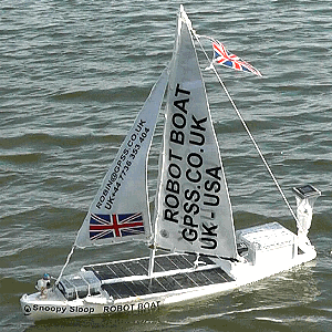
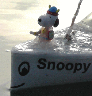
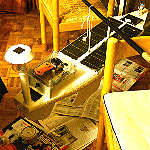
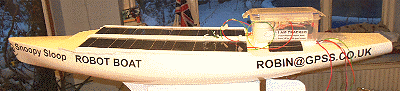
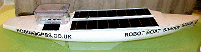
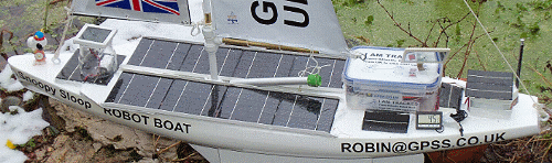
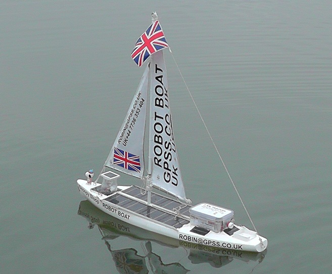
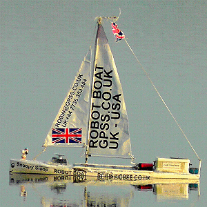
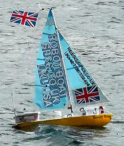
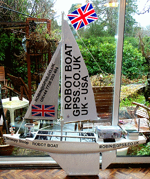
This page was started, back in 2012, to document the design of Snoopy Sloop 8 (on right), that made the short-lived attempt on the Atlantic in November 2012. A similar boat, called "9" then "10" after repair, made attempts in 2013, 2014 and 2015. This boat was rescued, twice from the Isle of Wight, then near Portland, and last Brighton. That's Snoopy Sloop 10 on the left. used for later attempts. After Boat 10 was lost, a very similar Boat 11 was used for following attempts each year.
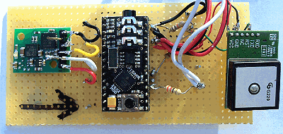
There are also linked detailed blogs of tests, repairs and modifications, of these boats. We stick to the existing design described on this page. When we make changes, they will probably be minor, such as using the Picaxe 28X2 and SPOT Trace. We have also switched to use of fewer, but better, solar panels.
One of the luxuries of being a "retired old man", with his career and business years behind him, is that I can afford to be very "up front" about my robot boat hobby work. I do not need to "hide my mistakes". Other Teams may need to show a more "professional" image - particularly if they have a business reputation to protect, or wish to attract research funding. I, however, can afford to make a public fool of myself :-)
 This page has mostly been for my own use, so I did not forget the important details of how parts
of the boat were put together, such as the modified SPOT tracker. I've tried to keep it up-to-date,
where minor changes, usually recorded in the blog, have been made. These are usually in the footnotes,
in the relevant section - but not always !
This page has mostly been for my own use, so I did not forget the important details of how parts
of the boat were put together, such as the modified SPOT tracker. I've tried to keep it up-to-date,
where minor changes, usually recorded in the blog, have been made. These are usually in the footnotes,
in the relevant section - but not always !
In December 2012, our priority was in finding Snoopy Sloop 8, and - if we did - having all the spares ready here to fix him. We were hoping to find, fix, and re-launch Snoopy before 1st January, so he was not disqualified from the Microtransat 2012 event. That's when I set up this page - to help myself remember some design detail ! Since boat 8 was never found, Snoopy needed another boat, and this next boat 9 was just like Snoopy Sloop 8 - the one that made the 2012 attempt. All boats were 24/7 tested for many months, before an Atlantic attempt.
There may soon be enough information here for someone, sufficiently daft, to build his own robot boat. My only request now: please don't expect a copy of our Team-Joker picaxe software, or put a Snoopy on your boat - unless you are a member of Team-Joker ! :-)
 The French Team ENSTA Bretagne boat, that competed in the 2012 Microtransat, is on the right.
The French originally suggested the Microtransat event.
Click on the picture to
enter the Microtransat Challenge pages, maintained by Colin Sauze at Aberwystwyth University in Wales, UK.
There you will see details of the boats taking part in each year's attempts.
The French Team ENSTA Bretagne boat, that competed in the 2012 Microtransat, is on the right.
The French originally suggested the Microtransat event.
Click on the picture to
enter the Microtransat Challenge pages, maintained by Colin Sauze at Aberwystwyth University in Wales, UK.
There you will see details of the boats taking part in each year's attempts.
For Americans, and old English (pre-metric) blokes like me: 1" = 25.4mm = 2.54cm = 0.0254m and 1 kg = 2.2 Lbs.
For younger "engineers" reading this page, please remember that old design principle
KISS = Keep It Simple, Stupid
:-)
For those interested in money: �1 = 1 GBP = 1 Pound Sterling = approx 1.2 Euro = approx. 1.6 USD.
For those irritated by Robin's landlubber terms, see Frank's
Terminology of yacht parts, fittings, etc.
- these pages will probably still use Robin's terms (e.g. "pointy end" instead of "bow") for our few women readers.
For landlubbers interested in speed: 1 knot = 1.15 mph = 1.85 kmph = 1.69 fps = 0.51 mps.
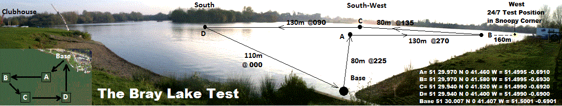
i.e. if Snoopy returns from waypoint B, via C, D, and back to base, in 15 minutes, that's about 0.7 knots.
![]()
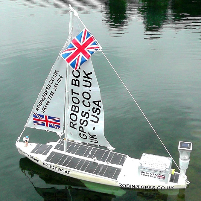
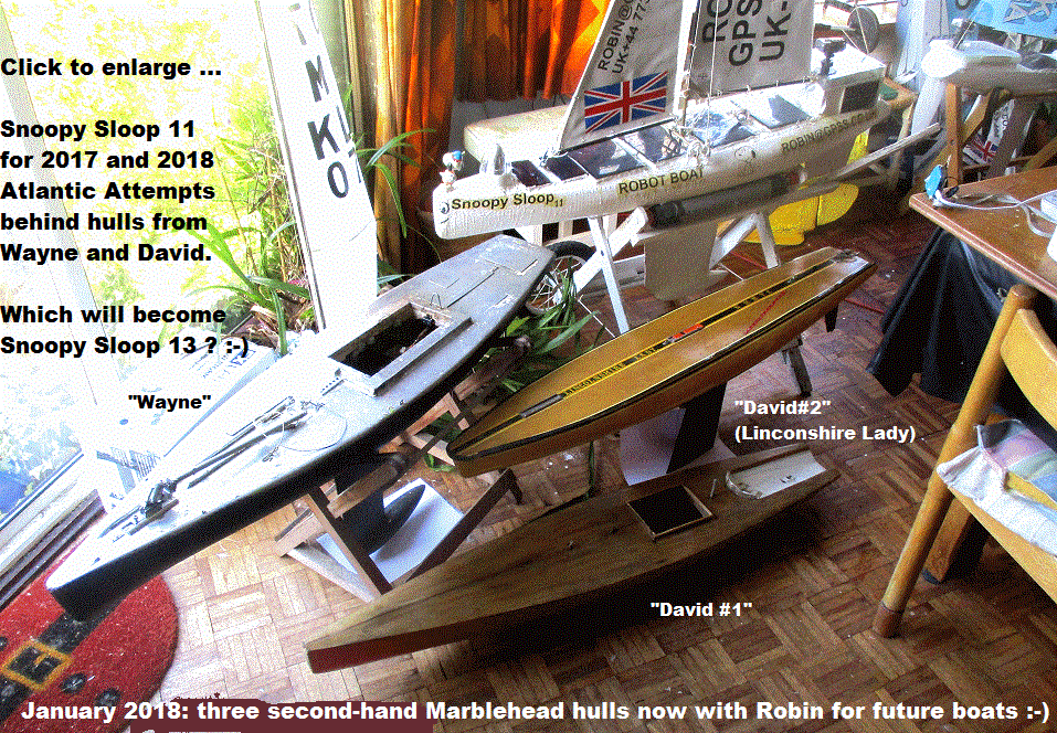
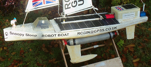
 from Robin in September 2024: this picture on the right shows Snoopy Sloop 11, built in 2014, and with those new solar panels: two pairs,
front and back, instead of on left and right. e.g. LHS (Left Hand Side) = Rear, and RHS (Right Hand Side) = Front. Wiring the same.
No need to change many other words here below - other than finding products, now "obsolete" :-)
from Robin in September 2024: this picture on the right shows Snoopy Sloop 11, built in 2014, and with those new solar panels: two pairs,
front and back, instead of on left and right. e.g. LHS (Left Hand Side) = Rear, and RHS (Right Hand Side) = Front. Wiring the same.
No need to change many other words here below - other than finding products, now "obsolete" :-)
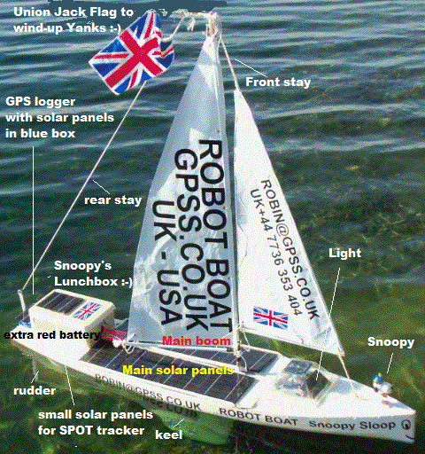
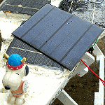
There is a lot I would not change in the next Boat. e.g. 1.2 metre long Marblehead hull with IOM #3 Storm sails; GPS-Only Autopilot, based on Picaxe computer and Globalsat BR355 GPS. I may experiment with new ideas, such as power switching, compass steering, and wind direction sensors - but they are only adopted after many months, or even years, of prototyping then thorough testing. I added this section so you don't miss important future changes, mostly based on the discovery of better products. So far they are: 1) Use of SPOT Trace, instead of a modified SPOT Messenger; 2) Use of the Picaxe 28X2 Computer, instead of the Picaxe 08M2: more memory and comes assembled; 3) Use of the Globalsat BR355-S4 GPS, including applying a firmware patch, and configuring it with Static Navigation off, and only $GPRMC sentences; 4) Fewer but better solar panels: "3.5W 6V 583mA Monocrystalline silicon Epoxy Mini Solar Panel DIY Solar Modu Y5E3" at < 4 GBP from China. 5) 1N5819 1A40V Schottky diodes .
RELIABILITY: The rudder servo is a critical element in Snoopy's robot boats. For years we used the Acomms AS-17 because tests showed high reliability of typically 8 to 12 weeks MTF in continuous* use. * typically 10 rudder movements per minute. When the AS-17 became obsolete and no longer available, I have used the Carson "Modelsport part No 50 050 2015. In 2024 Blog11 shows I had to use the Futaba S3003 - also "obsolete" ;-)
POWER CONSUMPTION: The rudder servos chosen draws an average of less than 7 mA, with small spikes during movement. The total electronics including Autopilot computer, Globalsat GPS, SPOT Tracking, is less than 40 or 50mA. This enables use of a small boat with limited deck space for solar panels.
You will see these products discussed in more detail, later on this "Design" page and linked pages. The pictures should help you find the relevant sections. See testing in Blog6 , Blog7 and BlogX . August 2024: Marblehead hull; Spot Trace; Picaxe 28X2; Bigger solar panels. other blogs include Blog and Blog11 :-)
![]()
![]()
 Experimental prototypes first sailed, on Bray Lake, in 2008, but it was not until 2012,
that we had settled on the current design, used in all our Atlantic attempts so far:
Experimental prototypes first sailed, on Bray Lake, in 2008, but it was not until 2012,
that we had settled on the current design, used in all our Atlantic attempts so far:
All products used within a boat will have undergone months, sometimes years, of experimental test, before weeks or months of 24/7 test, before an Atlantic attempt. Please do not confuse what we are doing experimentally, for possible use in future boats, with our "current design" above. e.g. experiments with boat 6 to test things like compass-based steering, use of wind direction sensors, etc.
Remember that the biggest challenge to a robot boat crossing the Atlantic is reliability: maybe the most useful thing to remember is "KISS" - Keep it Simple, Stupid :-)
Yes, the software in the Autopilot, just has to move the rudder to steer the boat. The following words appear much further down this page, talking about our "GPS Simulator" used to test the GPS->Computer->Rudder Servo system - including the software inside the computer ... QUOTE:
 The Autopilot logic may be described as:
The above cycle takes about 6 or 7 seconds, depending on how fast the boat is moving. Step 7 is done because the steering will be more sensitive if the boat is moving more quickly. This is to reduce "over-steering". Ideally the system should be tuned so that only one or two cycles are needed to turn the boat onto the required direction.
 UNQUOTE :-)
3a above says "play tones", but, in recent years, the autopilot software sends out text, that can be spoken by a TTS ( Text-To-Speech ) unit. The Autopilot computer has also changed, including iPAQ, Picaxe 08M, Picaxe 28X2, and Micromite. Robin's biggest mistake was not to buy enough spares, for the next boat. Products become "obsolete" - not because they are not good - but because they do not sell enough :-)
For the details of design, see the Robot Boat Blog Pages , but videos may be more helpfull - such as that on the right :-)
 Here is a summary of what is on this "design" page:
a. Blog of 24/7 Testing on Bray Lake, then the sea, including repairs and changes ... moved onto it's own Blog Page.
b. How we built Snoopy Sloop for Microtransat 2013 ...
c. Design and Spares - the major parts and sub-systems of Snoopy Sloop ...
 d. what bits have we used and where did we get them ? ...
e. Alternative Designs ...
f. room for a camera onboard ?
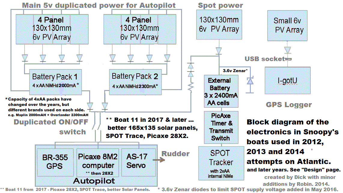
Here is a block diagram of the electronics used in boats 8, 9 and 10, used for 2012, 2013 and 2014 Atlantic Attempts ...
NOTE IN OCTOBER 2023: note big changes on things like SPOT power - Trace uses 4 NiMHd cells. No need for zenar diode.
This "blog" was getting huge, so has been moved into it's own Blog Page.
See the pictures above for the completed Snoopy Sloop 9.
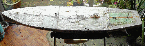
This new boat is almost identical to Snoopy Sloop 8. i.e. a 4 ft (1.2 metre) long marblehead hull, and 3 ft (1 metre) high sails. I spent �10 on a glass fibre hull from a local model boat club before Christmas. I managed to fill it with foam - without exploading the deck - by filling in several stages, and waiting for the foam to expand and set.
 There was no keel and rudder, so I made one, similar to that for boat 6. i.e. plywood with a steel tube filled
with lead, to give a weight of about 2.2 kg (this was increased to 3.7kg after the first test on Bray Lake).
Here is the hull and keel, before painting - and after. The plywood fairing at the front
is to protect the solar panels, which are wider than the deck at that point.
There was no keel and rudder, so I made one, similar to that for boat 6. i.e. plywood with a steel tube filled
with lead, to give a weight of about 2.2 kg (this was increased to 3.7kg after the first test on Bray Lake).
Here is the hull and keel, before painting - and after. The plywood fairing at the front
is to protect the solar panels, which are wider than the deck at that point.
 A coat of International Perfection two-part polyurathane (snow white) paint was used. The "seven dwarves" colour
was not available. The black vinyl labels were stuck on the hull and protected with clear varnish.
A coat of International Perfection two-part polyurathane (snow white) paint was used. The "seven dwarves" colour
was not available. The black vinyl labels were stuck on the hull and protected with clear varnish.
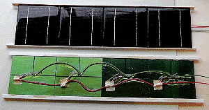
The two solar panel assemblies were contructed, each from four 130x130mm 6v/250mA solar panels. Silicon sealant was used to glue the four panels into the lightweight L-shaped plastic rails. The blocking diodes and wires were soldered onto the panels and joints protected by duck tape patches, before securing with super-glue, then fast glass resin, and then a coat of yacht varnish. The rear surface then got extra protection from silicon sealent, before the two panels were glued onto the deck with sealant.
 Snoopy Snoop 8 had it's main 5v power based on several 5v packs connected in parallel.
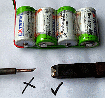
The four 10AH D-sized cells are a neater way of providing a large capacity 5v battery.
These "Extreme" 10000mAH (10AH) packs were a good buy on e-bay at �20.
When soldering wires onto the cells, you will need a soldering iron that is big enough !
The 4-cell pack was then protected by varnish and sealant before putting low into the hull.
 A similar approach was used for the SPOT tracker 3.6v battery, made from three D-sized 10AH cells,
to be charged by two, smaller 5v solar panels, mounted either side of the lunchbox.
A similar approach was used for the SPOT tracker 3.6v battery, made from three D-sized 10AH cells,
to be charged by two, smaller 5v solar panels, mounted either side of the lunchbox.
Note in May 2014: SADLY, THESE 10AH EXTREME CELLS MADE IN CHINA WERE EXTREMELY UNRELIABLE :-( DETAILS IN THE BLOG.
The picture on the upper-right was taken on 20th January, before wires were connected: no black smoke ! :-) The one below, taken next day, was after autopilot added inside wired-up lunchbox. The bath test looked good: waterline just touched the back, and touched the front below the S of Sloop, 4" back from the prow. We were "on target" for total weight to be less than 10kg, but, after increasing the keel bulb weight to 3.7kg, the total boat is now 12.3kg, like boat 8.

Snoopy is now screwed firmy on deck at the front.
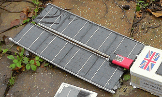
The solar light is based on the same, bright garden light product from Homebase, with better batteries. Instead of the pyramid-shaped pudding bowl, I used a sawn off plastic beaker, mounted on a CD. The battery is covered in silver foil and the lot glued together with silicon sealant. It was tested in the garden, watched by CCTV, to see if it stayed on all night. The final result was addition of one 130x130mm solar panel.
The GPS logger with it's solar panel has been added. See details including picture under "Design and Spares" below.
 The PICAXE-based timer for the SPOT tracker has been assembled and loaded with software.
It is now under calibration test, so the timing can be made as accurate as possible (typically 1 sec per day).
The SPOT tracker has been registered, modified, and is now being tested with the picaxe timer.
The loudspeaker seen here is to play "Popeye the sailerman" prior to each hourly transmission, to check timing accuracy.
The updated SPOT map is
here.
The PICAXE-based timer for the SPOT tracker has been assembled and loaded with software.
It is now under calibration test, so the timing can be made as accurate as possible (typically 1 sec per day).
The SPOT tracker has been registered, modified, and is now being tested with the picaxe timer.
The loudspeaker seen here is to play "Popeye the sailerman" prior to each hourly transmission, to check timing accuracy.
The updated SPOT map is
here.
Small changes have been made carefully to the PICAXE Autopilot software, and will get a lot of re-testing. See footnote under "11. the PICAXE Autopilot Software" below, with link to a video of the software being tested with the GPS simulator.
 Robin has invested in a pair of "waders", at �50 from a fishing tackle shop, and with his old life-jacket (from 1971),
he is better equipped to go wading into the sea on April 1st this year.
Robin has invested in a pair of "waders", at �50 from a fishing tackle shop, and with his old life-jacket (from 1971),
he is better equipped to go wading into the sea on April 1st this year.
The ship-to-shore transmitter, only used for Bray Lake testing, has been put into a detatchable waterproof box, and details are documented in the section below: "12. the Ship-to-Shore transmitter".
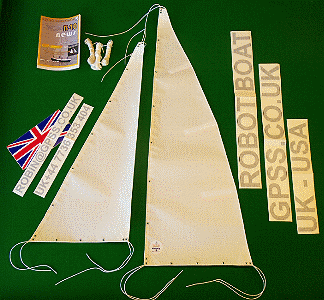
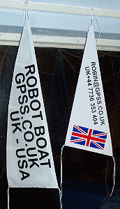
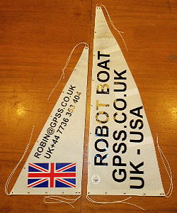
The incredibly strong sails, designed for the task, have arrived from Frank at Nylet - you can see they have MANY years of sail-making experience behind them :-) Here they are on my snooker table, minutes after arriving, with the sticky vinyl flags and letters to make them appear identical to the earlier boat.
On the right are the sails, after making opaque with a sheet of white sticky vinyl on one side, then applying the black sticky vinyl lettering on each side. Clear silicon sealant was added to reduce risk of letters pealing off.
 The sails have been added, to complete the boat, and strings smeared with clear silicon sealant.
Frank of Nylet, advises me "string" should be called "cordage".
This is braided Polyester cord (natural), via Nylet, sized
1.8mm; 2.0mm; 2.2mm. from English Braids Ltd. The largest 2.2mm size
was used from front deck, up the front of the jib to the top of the mast,
then as a rear stay to the hull at the stern. The next 2.0mm size
was used to lace the sails to their boom.
The sails have been added, to complete the boat, and strings smeared with clear silicon sealant.
Frank of Nylet, advises me "string" should be called "cordage".
This is braided Polyester cord (natural), via Nylet, sized
1.8mm; 2.0mm; 2.2mm. from English Braids Ltd. The largest 2.2mm size
was used from front deck, up the front of the jib to the top of the mast,
then as a rear stay to the hull at the stern. The next 2.0mm size
was used to lace the sails to their boom.
Here is the boat, in the snow, being tested in the garden. That aluminium tube with a green end, is a detatchable handle to lift the boat, via a loop of string. Two other things will not sail: the thermometer on the deck, and the mirror on the lunchbox lid, above the SPOT light - both so tests can be done from indoors, without needing to go out into the cold. I'm now testing the effect of temperature on the timing of hourly SPOT transmissions: so far, all done indoors at nearer 15C to 20C.
The new boat had it's first sail on Bray Lake on 13th February 2013. Here below, is the boat soon after launch. More lead was needed for the keel bulb
(increased from 2.2kg to 3.7kg),
and the jib was let out a little. Two days later, on the Friday, Snoopy completed the "Bray Lake Test", sailing around the lake,
then, at 1pm, was launched in "Snoopy Corner" to begin a few weeks of 24/7 reliability testing.
 This section describes the boat Snoopy Sloop that sailed in November 2012, known to Robin as "boat 8". Footnotes cover boat 9,
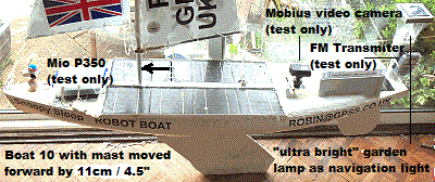
seen here on the right, during it's first test sail on 13th February. Click on the picture for a later one, without the FM Transmitter.
This section describes the boat Snoopy Sloop that sailed in November 2012, known to Robin as "boat 8". Footnotes cover boat 9,
seen here on the right, during it's first test sail on 13th February. Click on the picture for a later one, without the FM Transmitter.
You can see that the new box could be a larger, particularly across the hull. It cannot be much smaller, because there would not be space for what goes inside. The rudder post comes up into the box from the rudder, so it can be driven by the servo.
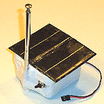
My wife June advises me that Snoopy's Lunchbox was part of a wedding present given to us in 1971: a small part in a large picnik hamper. Consequently it is not easy, if not impossible, to find a spare, today. I settled on this box during our 5,000 miles of 24/7 reliability testing on Bray Lake after April 2012, and long before we launched Snoopy near the end of November.
I chose it, from what I found in our kitchen cupboards, and after trying all the obvious alternatives, like contructing the box myself, use of Peleboxes, etc. The box was ideal because of it's lid: the two vertical surfaces, on lid and box, are flush, and it's convenient to stretch PVC insulating tape around it, before smearing with silicon sealant. Before you scoff - remember the time we've spent testing so far ! :-)
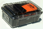
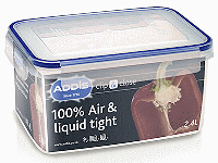 In late 2012, I ordered the ADDIS 2.4L boxes (Clip and Close: 220mmx160mmx110mm deep)
at 8 GBP each, after a successful overnight underwater test of a 2L sized box found in the kitchen.
This box is higher, so would be recessed into the hull - unless we find a shallower box.
If this product is suitable, I will have two spares :-)
In late 2012, I ordered the ADDIS 2.4L boxes (Clip and Close: 220mmx160mmx110mm deep)
at 8 GBP each, after a successful overnight underwater test of a 2L sized box found in the kitchen.
This box is higher, so would be recessed into the hull - unless we find a shallower box.
If this product is suitable, I will have two spares :-)
 Footnote in February 2013: I ended up using the 2L box, since it was already high enough. The material of the ADDIS box is polypropylene
and few glues, if any, will stick to it. The upper picture is inside the box on boat 8, in 2012, and the lower picture
is that on the new boat for 2013.
Footnote in February 2013: I ended up using the 2L box, since it was already high enough. The material of the ADDIS box is polypropylene
and few glues, if any, will stick to it. The upper picture is inside the box on boat 8, in 2012, and the lower picture
is that on the new boat for 2013.
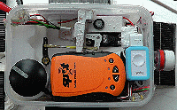
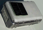
Footnote in October 2014: a year later, on 20th February 2014, the "lunchbox" was replaced by a waterproof "FIBOX TA201610T Enclosure" and this was reported in Blog2. The picture from the blog is on the left.
The GPS Logger was only added to comply with the Microtrasat 2012 rules.
 The GPS Logger is an off the shelf I-GotU Travel Tracker
from Maplins at approximately �45, together with it's USB cable, intended to be plugged into
a PC for data download and charging the internal battery. The USB cable plugs into a USB socket,
with the +5v and 0v pins connected to the small 6v solar panel on the lid of it's blue plastic box.
The solar panel is 6v 100mA 100x55mm. (link elsewhere on Robin's pages).
The panel is positioned so as not to obscure the GPS in the I-GotU, and so
it is possible to see that it is still working when tested. i.e. red power light comes on when
battery is being charged by the solar panel, and a regular blue flashing light to show
logger is working. The software with the I-GotU is set to record positions every 15 minutes,
cyclicly. i.e. with a capacity of years. The blue transparent box is sealed with transparent silicon sealant,
and that was used to fix the box to the rear deck. This was subject to the 24/7 testing on Bray Lake, as
part of the total boat system.
The GPS Logger is an off the shelf I-GotU Travel Tracker
from Maplins at approximately �45, together with it's USB cable, intended to be plugged into
a PC for data download and charging the internal battery. The USB cable plugs into a USB socket,
with the +5v and 0v pins connected to the small 6v solar panel on the lid of it's blue plastic box.
The solar panel is 6v 100mA 100x55mm. (link elsewhere on Robin's pages).
The panel is positioned so as not to obscure the GPS in the I-GotU, and so
it is possible to see that it is still working when tested. i.e. red power light comes on when
battery is being charged by the solar panel, and a regular blue flashing light to show
logger is working. The software with the I-GotU is set to record positions every 15 minutes,
cyclicly. i.e. with a capacity of years. The blue transparent box is sealed with transparent silicon sealant,
and that was used to fix the box to the rear deck. This was subject to the 24/7 testing on Bray Lake, as
part of the total boat system.
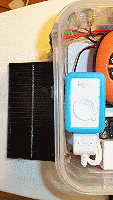
Footnote in January 2013: Exactly the same solution is used, with an I-GotU Travel Tracker from Maplins, connected via it's USB cable, to a small solar panel. However, instead of a seperate (blue) box, the I-GotU is inside Snoopy's lunchbox, and the solar panel is mounted on the deck, behind the lunchbox. See picture on right. Also, instead of being set to log GPS position every 15 minutes, it is set to record every 12 minutes. It holds 65,000 waypoints, so this holds the last 1.48 years (nearly 18 months) of GPS track.
The solar powered light was only added to comply with the Microtrasat 2012 rules.
 The light switches on automatically at dusk, gives a 360 degree continuous white light,
and switches off automatically at dawn. It is based on the LEDs, electronics and solar
panel from a garden centre solar light chosen for having brighter LEDs than others.
The two AA unbranded
batteries were discarded and replaced by two higher capacity 2000mAH NiMH cells.
The original enclosure was discarded and an assembly, with an additional four solar
panels around the side, was built into an upside-down pyramid shaped plastic pudding bowl.
Transparent silicon sealant was used to join the assembly to the bottom cut out of plastic.
The additional solar panels, were 4v 80mA 65x65mm connected via blocking diodes to the battery.
Transparent silicon sealant was used to fix the light to the front deck.
This was subject to the 24/7 testing on Bray Lake, as part of the total boat system.
The light switches on automatically at dusk, gives a 360 degree continuous white light,
and switches off automatically at dawn. It is based on the LEDs, electronics and solar
panel from a garden centre solar light chosen for having brighter LEDs than others.
The two AA unbranded
batteries were discarded and replaced by two higher capacity 2000mAH NiMH cells.
The original enclosure was discarded and an assembly, with an additional four solar
panels around the side, was built into an upside-down pyramid shaped plastic pudding bowl.
Transparent silicon sealant was used to join the assembly to the bottom cut out of plastic.
The additional solar panels, were 4v 80mA 65x65mm connected via blocking diodes to the battery.
Transparent silicon sealant was used to fix the light to the front deck.
This was subject to the 24/7 testing on Bray Lake, as part of the total boat system.
 Footnote in February 2013:
The new solar light is based on the same, bright garden light product
from Homebase, with better batteries. Instead of the pyramid-shaped pudding bowl, I used a sawn off plastic beaker,
mounted on a CD. The battery is covered in silver foil and the lot glued together with silicon sealant.
The result is smaller and lighter than the original.
Footnote in February 2013:
The new solar light is based on the same, bright garden light product
from Homebase, with better batteries. Instead of the pyramid-shaped pudding bowl, I used a sawn off plastic beaker,
mounted on a CD. The battery is covered in silver foil and the lot glued together with silicon sealant.
The result is smaller and lighter than the original.
I tested how well the original solar panel kept the light running all night, and soon added one 130x130mm panel, under the beaker. Wires were also soldered onto the two AA Ni-MH cells, and a 2.4v monitor point provided for test.
 Footnote added in August 2013: I think my next solar light will be based on this "superbright" product from Homebase (left).
After months of testing in the back garden, watched by CCTV, it works perfectly - staying on from dusk to dawn,
even after days with little sunshine. This worked "straight out of the box", without even changing the three cheap 800mAH AA batteries.
At 15 GBP, instead of 7.50 GBP, it was well worth the cost: no need to add an extra solar panel - and less work ! :-)
Footnote added in August 2013: I think my next solar light will be based on this "superbright" product from Homebase (left).
After months of testing in the back garden, watched by CCTV, it works perfectly - staying on from dusk to dawn,
even after days with little sunshine. This worked "straight out of the box", without even changing the three cheap 800mAH AA batteries.
At 15 GBP, instead of 7.50 GBP, it was well worth the cost: no need to add an extra solar panel - and less work ! :-)
Footnote in May 2014: we are using the Homebase "ultrabright" product, which was less weight and almost as bright.
Footnote in October 2014: by March 2014, our Blog2 shows us having adopted the "Ultra" garden lamp product (right). Replacements can now be purchased in Homebase for �3.50 ! :-)
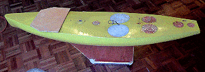
I'm sure there are better ways of making the hull of Snoopy Sloop. Maybe having it carved out of a solid block of suitable foam. But we did not have the means of doing this, so we used a second-hand marblehead boat off ebay. This was a LOT of work.
The hull is the part of Snoopy Sloop which was most work, to get it to the stage where we think it might survive many months at sea. We found many problems, we did not expect, only appeared after a few weeks of our 24/7 testing on Bray Lake. This was where Snoopy Sloop was left sailing continuously, back and forth across his 24/7 waypoint, in winds gusting up to 50mph.
Number one priority for any boat is that it should not sink. This has happened twice to Snoopy - checkout that "Snoopy Sails!" video on our front page! On these two occasions, it was we were too eager to put Snoopy on the water - before we had made the boat unsinkable by filling it with foam. The Titanic would not have sunk if filled with foam - but then there would be no room for passengers. If you squirt the foam into the hull, beneath an existing deck, it will all burst appart when the foam dries and expands to many times in volume. We've been there, and done that ! :-)
 So, after exploding the deck, we rebuilt up the inside where needed, from the existing keel and mast supporting block, to where
we could securely attach the rings onto which to tie things like jib, main sheet (string to main sail boom), and rear stay.
These need to be strong enough so that there is no risk of them pulling out after months at sea. It is also convenient
if the boat can simply be picked up or lowered by it's mast, or these strings. i.e. no special handle on the deck.
So, after exploding the deck, we rebuilt up the inside where needed, from the existing keel and mast supporting block, to where
we could securely attach the rings onto which to tie things like jib, main sheet (string to main sail boom), and rear stay.
These need to be strong enough so that there is no risk of them pulling out after months at sea. It is also convenient
if the boat can simply be picked up or lowered by it's mast, or these strings. i.e. no special handle on the deck.
The process of the foam expanding, without a deck to pull the hull sides together, had the additional benifit of widening the top of the hull to above the required 280mm/28cm/11" needed for two rows of 13cm wide solar panels plus a centimetre to leave space for mast hole(s) and where the main sail boom is tied. However, in this picture above, you will see that piece of plywood was needed to protect the solar panels where the hull deck was too narrow.
The position of the fixings, and hole for the mast (brass tube, to receive the brass tube on bottom of mast) is obviously driven by the size of the standard IOM #3 sails, not having the main boom hit the lunchbox at the back, and - very important - the sailing "balance" of the boat. i.e. not turning into wind, or away from wind, for as wide a typical wind strength as possible.
One company has offered to produce just the solid foam hull, if they are supplied with CAD (Computer-Aided-Design) data as "are, stp, iges, wkf, stl, obj" files for input to their Numerically Controlled Machine. A typical price to us might be as little as 600 GBP including VAT. This is for a foam hull of about 1.3 metres (4 feet) long. The CAD data would need to be done by someone else, working from whatever sketches or photos are available. After receipt of the foam hull, from this company, more work must be done, such as adding the keel, framework for fixing stays, and any other surfacing - if needed - such as a "skin". Another company has offered to provide just the fibre-glass hollow hull, into which lead shot must be poured (for the keel weight) before expanding foam, such as that we squirted into our 45 GBP second-hand marblehead hull.
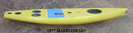 Footnote: fibreglass hull for �10 : I've now got this yellow 1977 Marblehead hull for �10 from
Woking Model Yacht Club.
Next job is to add a keel, fixings, and fill with foam.
The red
Monarch
in their advert may get sold back (�40 ONO),
since it's a bit too narrow for solar panels. It's here to collect :-)
Footnote: fibreglass hull for �10 : I've now got this yellow 1977 Marblehead hull for �10 from
Woking Model Yacht Club.
Next job is to add a keel, fixings, and fill with foam.
The red
Monarch
in their advert may get sold back (�40 ONO),
since it's a bit too narrow for solar panels. It's here to collect :-)
Footnote in January 2013: See the "how we built ..." section above for how this new hull was used.
The keel came with the marblehead hull, and nothing other than sealing and painting was done with it.
We had "interesting experiences" with our rudders, after they had been in the water for a few weeks.
 We found that water must have soaked into the araldite that we used to glue the shaft into the rudder.
There were several occasions where the rudder started to rotate on it's shaft.
On one occasion the rudder dropped off when two local schoolboys "stole" the boat,
that had drifted in when the wind dropped. They took it home and into their back garden.
They then 'phoned me, asking if there was a reward. I saw where they were with the tracker,
and they did get a small reward - for advice on what labels we add: "I am tracked!"
My wife and I found the rudder, floating near the bank, where it had been tracked to.
We found that water must have soaked into the araldite that we used to glue the shaft into the rudder.
There were several occasions where the rudder started to rotate on it's shaft.
On one occasion the rudder dropped off when two local schoolboys "stole" the boat,
that had drifted in when the wind dropped. They took it home and into their back garden.
They then 'phoned me, asking if there was a reward. I saw where they were with the tracker,
and they did get a small reward - for advice on what labels we add: "I am tracked!"
My wife and I found the rudder, floating near the bank, where it had been tracked to.
The shaft was of the standard diameter used in such model yachts, to receive a standard servo lever at the top, where it comes into the "lunchbox" of electronics.
We used steel rod resined into brass tube of the correct diameter.
The final solution involved a brass plate, soldered and resined to the brass tube, to ensure the shaft would not twist in the rudder. String was then wrapped around the assembly, before fastglas resin was used, before the white paint.
Next time we may put some kind of rudder guard, such as rod from back of keel weight, to the upright support for the rear stay. It is easy to damage the rudder, or simply knock it, so it twists in the lever at the top.
Footnote in January 2013: See the "how we built ..." section above for the details of new keel and rudder.
The sails were based on a set of standard International One Metre (IOM) number 3 storm sails. Almost all our sails were from House Martin Sails (see bits below). After a few weeks of 24/7 testing, we soon saw signs of fraying, so strengthened the sails by sticking sheets of sticky white vinyl either side. At same time we inserted strong string, and also brass eyelets. This had the extra benefit of making the sails opaque, so the viewer is not confused by the black text on the other side of the sail !
When choosing material to make the sails, remember it has to be strong - but also please remember that we need to stick on those labels - using black sticky vinyl letters. So this means the outer surface will probably need to be some type of white plastic.
The mast was far from obeying IOM rules: it was made as strong as possible, the centre being solid carbon fibre rod, surrounded by aluminium tube, and plastic tube of a diameter to match the diameters. The joint between mast and main boom is based on a plastic Hoselock T piece from a garden centre - but strengthened with Isopon P40.
We soon dispensed with the complication (and resulting unreliability) of a sail winch servo. The sails are always set for tacking. For us, having both booms swing out to about 30 degrees seemed best. An additional benifit is that, when sailing downwind, in the strongest of winds (we have filmed it doing 24/7 tests in up to 50mph) it is less likely to somersault - a known hazard by model boaters we believe! It obviously may "jibe" more often, but that's a consequence we have to live with.
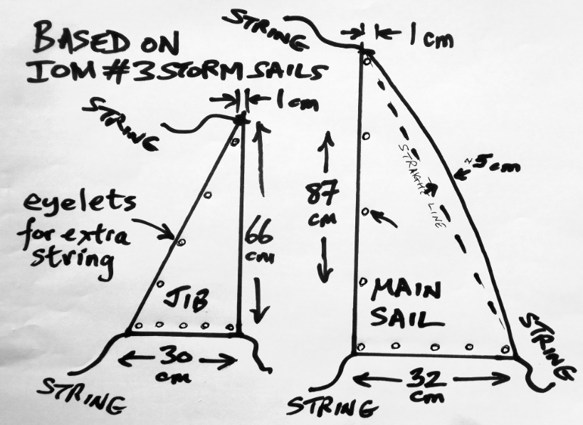 Here are some dimensions:
 Footnote in February 2013:
The incredibly strong sails (above), designed for the task, arrived from Frank at
Nylet - you can see they have MANY years of sail-making experience behind them :-)
Here they are on my snooker table, minutes after arriving, with the sticky vinyl flags and letters to make them
appear identical to the earlier boat.
Footnote in February 2013:
The incredibly strong sails (above), designed for the task, arrived from Frank at
Nylet - you can see they have MANY years of sail-making experience behind them :-)
Here they are on my snooker table, minutes after arriving, with the sticky vinyl flags and letters to make them
appear identical to the earlier boat.
On the right are the sails, after making opaque with a sheet of white sticky vinyl on one side, then applying the black sticky vinyl lettering on each side. Clear silicon sealant was added to reduce risk of letters pealing off.
The cordage (or "string") is braided Polyester cord (natural) from English Braids Ltd via Nylet: Sized 1.8mm; 2.0mm; 2.2mm. The largest 2.2mm size was used from front deck, up the front of the jib to the top of the mast, then as a rear stay to the hull at the stern. The next 2.0mm size was used to lace the sails to their boom. Silicon sealant was smeared on the cordage after it was in place, to reduce the risk of fraying.
Footnote in January 2014: the above sails, made from dacron, and covered in vinyl, have survived well, including many weeks of 24/7 testing on Bray Lake, and three visits to the sea in 2013. Robin ordered a spare set from Frank, and these arrived in January 2014: see the picture on left and blog. Frank has modified the design of these "Atlantic IOM #3" sails, so we don't need to cover them with vinyl to make them opaque. They consist of a double layer dacron "sandwich" with silver spray paint on the inside surfaces. There is also extra cross-stitching, and plastic braces, to further increase strength.
The words and pictures, under "Early prototypes" below, have been on this web site since early 2012. More recently, I said here: " I may put up more detail on the modifications, including the picaxe based timer, used to initiate the spot position reports. But this will be after checking with SPOT LLC that they have no objection: they may prefer that people do not use their spot tracking service in this way. ". I've received no reply in over 10 days, and so I am now publishing the details of design modifications that I made, that "seemed to work for me". My changes described below are often "against the rules". e.g. trickle charging of Ni-Me batteries from a solar panel. You use this information at your own risk ! :-)
 These pictures and text were on our
robot boat page in the summer of 2012, and show how we first modified the tracker.
These pictures and text were on our
robot boat page in the summer of 2012, and show how we first modified the tracker.
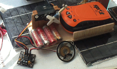
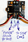
"On left you see a very crude means of making the SPOT Messenger send regular position reports,
currently every hour. A PICAXE based timer (on left) operates a servo
to press the "OK" button on the SPOT to initiate a position report. The small loudspeaker is just for test
- to play "Popeye the sailorman" just before transmission :-)
A tidied up version of this SPOT tracker, was put in boat 8 for 24/7 tests on Bray Lake,
until the SPOT Messenger eventually failed, after months of continuous operation.
We now have a Mk2 version in the boat that does not need a servo. It has also been running for months".
The SPOT tracker needs to run for many months, for the duration of the Atlantic crossing - maybe for as much as a year! I made changes to the tracker, such as the batteries inside, additional ones outside, and a small solar panel so that the system SHOULD remain working indefinitely - IF it is not soaked with water, after the boat is dashed on rocks!
Soon after getting my first SPOT messenger, in early 2012, I did some simple power tests with a meter:
when switched off, I could see no current drawn; when switched ON, it drew about 2mA - due to flashing the "on" LED;
when I pressed the [OK] button, it drew about 80mA* for the 15 minute SPOT transmission cycle.
So this told us the approximate power needed from batteries and solar panels: it depends on how often
you transmit. If at the maximum rate, of every 15 minutes, it averages about 80mA. If every hour
(the period I decided on) it's about 20mA. If once per day, it's nearer to 3mA. Every hour seemed
a good choice, to ensure we got regular position updates, even if some messages were lost. i.e. 20mA.
* in January 2015, measurement showed 30mA instead of 80mA - indicating an average consumption of less than 8mA.
See footnote below.
I replaced the two reccomended 1.5v Lithium AA cells by rechargeable Ni-Zn (Nickel-Zinc) cells from Maplin. They need their own special charger, and are not reccomended to be used as we did! When fully charged, these two cells give about 3.6v - way above the reccomended batteries.
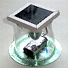
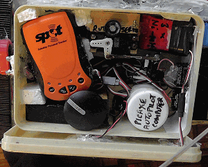
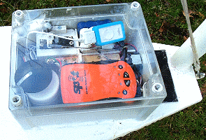
 On the left you see our Mk2 SPOT tracker prototype, with it's solar panel, in a watertight Peli 1050 box.
We found the sun made it a little too hot inside the box, so we painted the iside of the box white and
put the solar panel on the outside. We soon added a second solar panel.
On the left you see our Mk2 SPOT tracker prototype, with it's solar panel, in a watertight Peli 1050 box.
We found the sun made it a little too hot inside the box, so we painted the iside of the box white and
put the solar panel on the outside. We soon added a second solar panel.
Two small solar panels, nominally 6v and 80mA output, in parallel, seemed enough to keep the batteries topped up for months of typically English dull weather. To be more certain, and at risk of "blowing something up", an external battery pack was added, of three Ni-MH (Nickel Metal Hydride) cells, giving a nominal 3 x 1.2 = 3.6v. Both Ni-Zn and Ni-MH packs were seperately charged and "balanced" before connecting together, and to the solar panels. I saw no "white smoke", and this solution seemed to work reliably for many months of continuous use.
Footnote in May 2014: the blog records minor changes to the SPOT power supply during the rebuild of boat 9
to make boat 10. A single 3 cell NiMHd battery (3.6v) is clamped with 3.7v zenar diodes, and connects
into the SPOT internal supply. The NiMHd battery is charged from a single 6v 250mA solar panel at the front
of the boat, and also from the main 5v supply, via a series 11 ohm resistor, and two diodes to drop 1.4 volts.
7th January 2015: measurements on the spare Spot4 tracker showed < 30mA instead of 80mA.
All our trackers have been based upon the old "Spot Messenger 1", and not later Messenger products.
Either our measurements back in 2012 were wrong, or maybe the Spot Messenger 1 product was improved
over the years. These recent tests were done after seeing that the spare Spot4 was running more
days than expected on just internal batteries.
Both Mk1 and Mk2 of our SPOT tracker used the same type of PICAXE Servo Driver board as used for the autopilot. The Mk1 prototype used solar panels and Ni-Zn batteries for power, and a servo to press the [OK] button on the SPOT Messenger every hour. This worked reliably for several months of continuous use, until the SPOT device developed a fault: after a few seconds of startup tests, a red warning light comes on. The Mk2 version was working, long before that, and has been in continuous operation for months, reporting every hour, until after Snoopy hit the rocks on 27th November.
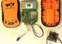
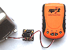
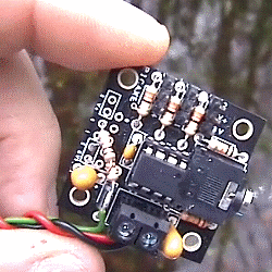
![SPOT tracker power and [OK] switch contacts](rbdessp2.gif) The three wires from the PICAXE Servo controller, that normally go to a servo, are connected
directly into the SPOT Messenger. The red and black power leads connect to the 3.5v SPOT power.
The voltage is normally sufficient to operate the PICAXE SPOT Timer.
The third (white) wire is soldered into one of the SPOT Messenger [OK] switch contacts via a 10k resistor.
The three wires from the PICAXE Servo controller, that normally go to a servo, are connected
directly into the SPOT Messenger. The red and black power leads connect to the 3.5v SPOT power.
The voltage is normally sufficient to operate the PICAXE SPOT Timer.
The third (white) wire is soldered into one of the SPOT Messenger [OK] switch contacts via a 10k resistor.
The Timer software program, inside the PICAXE, has a delay lasting 60 minutes, then operates the [OK] button, to start a position report transmision, then waits for another hour. The count to achieve the hour pause, accurate to about 1 second per day, was done by calibration tests for that particular PICAXE board, at the typical expected temperature, and with it's modified power supply. This is because the PICAXE speed varies with component tolerances, temperature, and power supply voltage.
 The actual software operation of the [OK] switch is a "LOW 4", "PAUSE 1 sec", "HIGH 4".
When this is done, you see the green [OK] LED flashing, in addition to the green [ON] LED,
so you know it has started the transmission cycle, lasting about 15 minutes.
This signal appears on the right hand size servo connector. See picture on right.
The left connector carries the "Popeye Tune" signal for test. In software as "TUNE 2".
The actual software operation of the [OK] switch is a "LOW 4", "PAUSE 1 sec", "HIGH 4".
When this is done, you see the green [OK] LED flashing, in addition to the green [ON] LED,
so you know it has started the transmission cycle, lasting about 15 minutes.
This signal appears on the right hand size servo connector. See picture on right.
The left connector carries the "Popeye Tune" signal for test. In software as "TUNE 2".
In the early version of the Timer software, we started with the [OK] operation, before the 60 minute delay. We saw that, if the battery voltage started to fall, due to too many days without sunlight, the SPOT transmissions speeded up, to every 15 minutes, until they stopped completely. This was because the PICAXE did not have enough voltage to operate. This effect was good - in that we could see the problem occuring - but accelerated the system stopping completely, because the average power drain will have gone up four-fold, to nearer 80mA from 20mA. A simple software change, to operate the [OK] button AFTER the 60 minute delay, meant that, if voltage dropped, the SPOT stopped reporting, and drawing power, until the solar panels had recharged it sufficiently.
Footnote in January 2013: The SPOT tracker has been registered, modified, and is now being tested with the picaxe timer.
The loudspeaker seen here is to play "Popeye the sailerman" prior to each hourly transmission, to check timing accuracy.
The updated SPOT map is
here.
Note that it is EXTREMELY difficult to solder the 10k resistor into the SPOT board because everything is so small, including how close the printed circuit track is to the ground plane. Make sure this is a clean connection, with no short to the ground plane or elsewhere.
The SPOT servo lead plugs into the right hand position on these photos. The left hand position outputs sound of "Popeye the Sailorman", lasting about 3 seconds, immediately before the hourly "pressing" of the SPOT [OK] switch, to start a transmission cycle.
Footnote in April 2016: the following is from my "AVL" page. SPOT Trace looks a much simpler and better solution ...
In March 2016 I discovered the
SPOT Trace
at 78 GBP. It looks as if it could be a much neater solution
than our modified SPOT Messenger + Picaxe Timer used for tracking Snoopy's robot boats,
far out to sea, including mid-Atlantic.
SPOT Trace requires the usual SPOT service contract, costing about 100 GBP per year.
See the
SPOT Trace User Guide for details
such as power consumption. It seems a small solar panel and 4 NiMH cells should be enough to keep the SPOT Trace running,
even if it were reporting position every 5 or 10 minutes.
The only snag found is that SPOT Traces includes a movement sensor,
which suppresses position reports if there no movement detected.
This is an inconvenience if doing 24/7 testing on lakes under all weather
conditions, including very light wind.
More details can be found on
BlogX,
Snoopy's Experimental Blog page.
 In the early years, our autopilot was based on an iPAQ Pocket PC, running Microsoft Windows Mobile and Robin's
GPS Software for Pocket PC called
GPSSppc.
You will see and hear this solution described and being used in the "Snoopy Sails!" video linked
from pages such as
Robin's Snoopy Sloop robot boat - the early years, from 2008 to 2010
These early autopilots were based on the computer controlling a vane-rudder, and in May 2011
Snoopy Sloop 5 was completing the Bray Lake Test, sailing between waypoints. See further down our
main robot boat page for details, GPS plots, etc.
In the early years, our autopilot was based on an iPAQ Pocket PC, running Microsoft Windows Mobile and Robin's
GPS Software for Pocket PC called
GPSSppc.
You will see and hear this solution described and being used in the "Snoopy Sails!" video linked
from pages such as
Robin's Snoopy Sloop robot boat - the early years, from 2008 to 2010
These early autopilots were based on the computer controlling a vane-rudder, and in May 2011
Snoopy Sloop 5 was completing the Bray Lake Test, sailing between waypoints. See further down our
main robot boat page for details, GPS plots, etc.
 It was then that we started to test a radically simpler PICAXE-based autopilot, described below, dispensing with the vane-rudder,
which we found too difficult to operate in strong winds (too much torque needed by the 360 degree servo),
and too difficult to make sufficiently robust. The PICAXE consumed far less power (1mA) than an iPAQ,
and it showed promise of being a simpler, more reliable, computer. Boat 6 was built for first tests of the
PICAXE autopilot, and also appears doing our first sea test.
It was then that we started to test a radically simpler PICAXE-based autopilot, described below, dispensing with the vane-rudder,
which we found too difficult to operate in strong winds (too much torque needed by the 360 degree servo),
and too difficult to make sufficiently robust. The PICAXE consumed far less power (1mA) than an iPAQ,
and it showed promise of being a simpler, more reliable, computer. Boat 6 was built for first tests of the
PICAXE autopilot, and also appears doing our first sea test.
The main problem with the PICAXE was squeezing the required software into a device with only 2KB of total program memory, and limitations such as only having unsigned integer arithmatic. However, the facilities already in the PICAXE for servo and serial input handling, together with the excellent support from people like "Hippy" on the PICAXE Forum, meant we soon got the solution working.
We started with a wind vane sensor, with tacking logic, and this all worked well. However, we eventually dispensed with the wind vane sensor because or tests showed that the boat still coped well "self-tacking" into the wind, without the sensor. This saved 30% of the power required (less solar panels) and also freed a lot of tight PICAXE memory when the tacking logic was removed. There is more detail on our Wind Vane Sensor here.
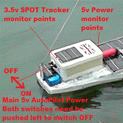
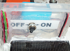
 The autopilot system is powered from the main 5v supply, consisting of NiMH batteries charged from the
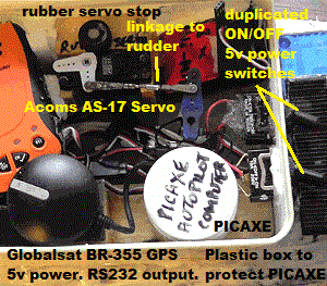
array of 8 6v solar panels, each 13cmx13cm. The power is switched on by two on/off switches, duplicated for reliability.
Normally these switches (protected by standard rubber sleeves) are left ON. Here they are both switched OFF.
The autopilot system is powered from the main 5v supply, consisting of NiMH batteries charged from the
array of 8 6v solar panels, each 13cmx13cm. The power is switched on by two on/off switches, duplicated for reliability.
Normally these switches (protected by standard rubber sleeves) are left ON. Here they are both switched OFF.
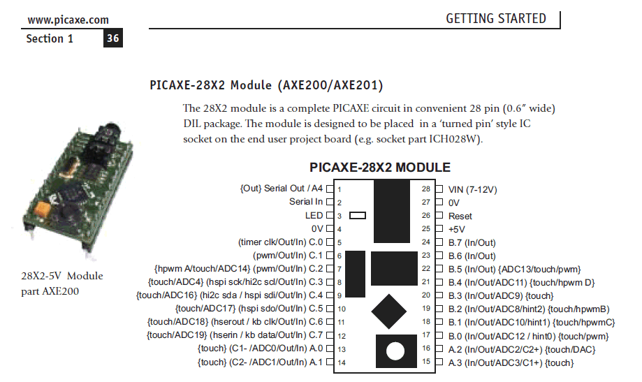
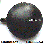
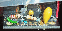
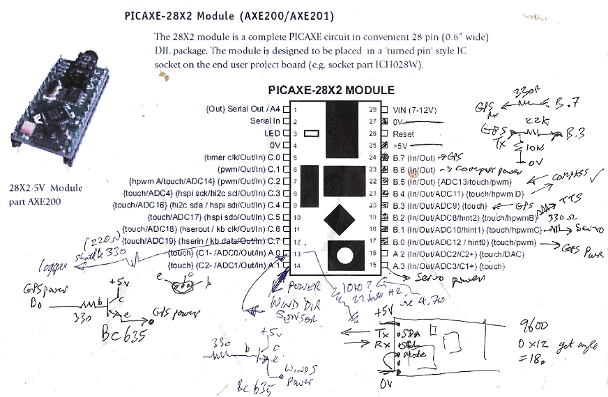
The Globalsat BR-355 GPS had it's DIN plug removed, to avoid risks of bad contact via plugs/sockets. Three wires are used: Red: +5v in; Black: 0v; and Green: RS232 signal out, into the PICAXE computer.
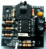 The GPS signal is fed to an input pin of the PICAXE, which is the "AXE024 servo driver kit" in our list of bits below.
The picture above-right shows the white GPS signal wire, connected to the picaxe board
via 22K and 10K resistors. The 22K connects the GPS signal to the point labelled "3" near "V+".
The 10k resistor connects the GPS signal to "oV" near the yellow capacitor on the right.
Note added in August 2013: The Picaxe AXE024 board has changed since the above was written, and my Autopilots were constructed,
using the v1 AXE024 kit.
For differences between v1 and v2 boards, see
AXE024 v1
and AXE024 v2.
For the v2 AXE024, the 22k resistor solders into the hole below "M" in "PICAXE.COM" - see white wire in photo on right.
The GPS signal is fed to an input pin of the PICAXE, which is the "AXE024 servo driver kit" in our list of bits below.
The picture above-right shows the white GPS signal wire, connected to the picaxe board
via 22K and 10K resistors. The 22K connects the GPS signal to the point labelled "3" near "V+".
The 10k resistor connects the GPS signal to "oV" near the yellow capacitor on the right.
Note added in August 2013: The Picaxe AXE024 board has changed since the above was written, and my Autopilots were constructed,
using the v1 AXE024 kit.
For differences between v1 and v2 boards, see
AXE024 v1
and AXE024 v2.
For the v2 AXE024, the 22k resistor solders into the hole below "M" in "PICAXE.COM" - see white wire in photo on right.
The middle position drives the rudder servo, to steer the boat, based on where it is, and the direction it needs to go.
A third output pin was used to generate tones, in the early months of testing, which were output to a small loudspeaker. An FM transmitter "bug" transmitted these sounds to a transister radio on the shore at Bray Lake. The pattern of tones, or tunes, gave information such as range to the next waypoint. e.g. "dah-dah-dit" = 50+50+10 = 110 metres; "Close encounters" film theme, when in the waypoint box. This software logic, loudspeaker, and FM transmitter, was removed, after we entered the phase of 24/7 reliability testing, of the final UK-USA version of the software.
The AS-17 servo was chosen because of it's low power drain and becauseit was a mass-market product - more likely to have a well tested design. For the many months of continuous use of these servos, the only time they failed was if water got into them. The servo is high in the box, in case some water does get in. During our 24/7 tests we did find one flaw (or "feature"?) of the servo: if the 5v power dropped very low (below 3v) due to prelonged days with little sun, there was a tendency for it to "creep" clockwise. If this went too far, our servo linkage risked "flipping over", reversing the rudder movement. When power restores, such as at dawn, the PICAXE restarts, but if this has happened, the rudder will not do as intended! Our solution was to introduce a rubber stop, to limit how far the servo can creep. Under normal use, and normal power input, the servo cannot reach the stop. This was done because it was considered it would take too many months of repeated testing with a different servo, to reach the same level of confidence in it.
 The Main 5v Power system for the autopilot consists of three NiMH batteries, in parallel, charged from the
array of 8 6v solar panels, each 13cmx13cm. The solar panels are sub-assemblies, supported by light weight L section
plastic strip. All panels are connected in parallel, with their own blocking diodes. The rear surface of the panel
(including the copper printed circuit) is protected by layers of FastGlass Resin, varnish and then silicon sealant
that is also used to fix the assemblies onto the deck.
The Main 5v Power system for the autopilot consists of three NiMH batteries, in parallel, charged from the
array of 8 6v solar panels, each 13cmx13cm. The solar panels are sub-assemblies, supported by light weight L section
plastic strip. All panels are connected in parallel, with their own blocking diodes. The rear surface of the panel
(including the copper printed circuit) is protected by layers of FastGlass Resin, varnish and then silicon sealant
that is also used to fix the assemblies onto the deck.
The total average power consumed by the autopilot is less than 50mA, with the majority drawn by the GPS (~35mA), very little by the PICAXE (~1mA), and a small ammount by the servo (~7mA but spikes of maybe 100mA when it moves). The loudspeaker and wind vane sensor were removed to reduce the power consumption by about 30% to these levels. these figures to be checked against Robin's old notes.
Early in our 24/7 testing on Bray Lake, started in April 2012, we used a single 2600 mAH 4xAA NiMH pack (as sold for use with radio control receivers). This small capacity was to test the total boat system in conditions where the power drops from it's nominal 5v (typically 5.2v), to as low as 3v, when parts like the PICAXE, GPS, and/or servo, will stop working. 2600mAH/50mA = approx 52 hours, so we occasionally got a low power condition during our tests. When the sun came up, the system would normally restart and be running again within two or three hours of dawn. This was when we verified that the system would cope with power failure. It was also when we discovered the "servo creep" problem, which resulted in our "rubber servo stop" solution.
We would have liked to continue using the high capacity 10,000mAH (10AH) D-sized cells, used in the early years. However, we soon found that any water ingress resulted in the containers rusting (cans contain steel?) and our soldered connecting wires breaking. It was obviously not a good idea to use the usual "spring" battery boxes. We decided to use only packs of "tagged" cells. Connectors, such as futaba servo plugs and sockets, were duplicated or triplicated.
Snoopy Sloop completed most of it's 24/7 testing, and was launched on it's Microtransat 2012 attempt, with three battery packs in parallel: two 2600mA flat packs of AA cells inside the box, under the spot tracker, and a larger, red, 4 cell sub-C 5100mA pack you see immediately in front of the lunchbox. i.e. a total capacity of about 10,300mAH or 10.3AH. The red, external pack was 4 cells, broken out of a 7 cell 8.4v pack from Hobby-Power.
Footnote from January 2013:
The two solar panel assemblies were contructed, each from four 130x130mm 6v/250mA solar panels. Silicon sealant
was used to glue the four panels into the lightweight L-shaped plastic rails. The blocking diodes and wires were
soldered onto the panels and joints protected by duck tape patches, before securing with super-glue, then
fast glass resin, and then a coat of yacht varnish. The rear surface then got extra protection from
silicon sealent, before the two panels were glued onto the deck with sealant.
The four 10AH D-sized cells are a neater way of providing a large capacity 5v battery. These "Extreme" 10000mAH (10AH) packs were a good buy on e-bay at �20. When soldering wires onto the cells, you will need a soldering iron that is big enough ! The 4-cell pack was then protected by varnish and sealant before putting low into the hull. A similar approach was used for the SPOT tracker 3.6v battery, made from three D-sized 10AH cells, to be charged by two, smaller 5v solar panels, mounted either side of the lunchbox.
Footnote in May 2014: SADLY, THESE 10AH EXTREME CELLS MADE IN CHINA WERE EXTREMELY UNRELIABLE :-( DETAILS IN THE BLOG.
 Even something as simple as the ON/OFF switch needs thought - and probably good 24/7 testing by us !
The main purpose of the power switch on Snoopy-Sloop is for convenience when testing. The autopilot can be switched OFF, to stop movement of the rudder, when transporting by car, to or from anywhere. It may also be useful, for a quick test that the system is all working: switching OFF then ON will result in the autopilot software doing a startup test, moving the rudder left-centre-right-centre.
When the boat is making an Atlantic attempt, or on 24/7 test, it will be left switched ON.
There is no problem if the switch fails in an ON state, but failing OFF (open circuit) is not good!
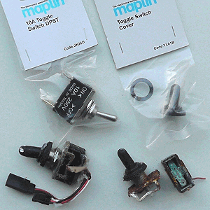
Here, in the picture, is the product used in Snoopy Sloop for the past year or two. I'm sure we can do better, such as use of a magnetic switch, as has been suggested by friends. The questions will be "what product?" and "how soon can we test it?" The magnet on the outside would turn the system OFF. Any such "magnetic key" would be kept somewhere else on the boat for a "finder". Why not change the switch now ? Because my approach is that ANY change to the boat needs to be properly tested, probably under our 24/7 conditions on Bray Lake.
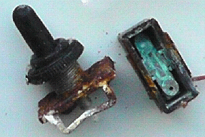 We've had two cases where that same big clunky switch failed in an OFF state, over the years
after water got into it, causing corrosion.
The failed switches are in the picture.
We tore one of the "broken" switches apart to confirm how corrosion inside killed it:
There was silver contacts in the obvious place, but not at the pivot point.
We've had two cases where that same big clunky switch failed in an OFF state, over the years
after water got into it, causing corrosion.
The failed switches are in the picture.
We tore one of the "broken" switches apart to confirm how corrosion inside killed it:
There was silver contacts in the obvious place, but not at the pivot point.
Of course, water should not get to the switch inside the box. But it's not a bad idea, when designing any system, to think of what happens when any part fails - such as our "lunchbox" springing a leak. Tell that to the designers of my old Mercedes, which gave all sorts of crazy computer warnings and symptoms, because of a broken earth wire! :-)
It would not have occurred to me that such a big clunky switch would fail OFF - even when water got inside. Similar things have happened for other parts of the boat system, such as how the rudder shaft is fixed to the rudder.
 I think 24/7 testing of the
total boat system was extremely valuable. Even leaving a boat tethered (or "anchored")
in a wind-exposed bit of water, might be a means of doing this, if you don't have the luxury
of a lake which has little risk of someone stealing the boat - although that has happened to us
- see my "keel and rudder" section above :-)
I think 24/7 testing of the
total boat system was extremely valuable. Even leaving a boat tethered (or "anchored")
in a wind-exposed bit of water, might be a means of doing this, if you don't have the luxury
of a lake which has little risk of someone stealing the boat - although that has happened to us
- see my "keel and rudder" section above :-)
Friends have suggested magnet "reed-relay" types of switch - which obviously need to be "normally-closed". I'll be interested if anyone knows any suitable ones, and a UK supplier - including via ebay. It would seem a good idea, to have two or three in parallel, inside the box, with a magnetic key, maybe on a length of string, that is placed against them, on the outside of the box.
 Footnote in January 2013: I guess I should have thought of this before: duplication of the switch INSIDE the switch.
This smaller double-pole switch provides the duplication (for reliability) inside the switch.
Each contact is only rated at 2A, but that's plenty more than the 0.1A maximum expected.
Footnote in January 2013: I guess I should have thought of this before: duplication of the switch INSIDE the switch.
This smaller double-pole switch provides the duplication (for reliability) inside the switch.
Each contact is only rated at 2A, but that's plenty more than the 0.1A maximum expected.
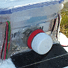
February 18th: switch cover was added, made from the top of a lemonade bottle. This should stop switch being knocked off by accident and also help water-proofing.
Please do not expect me to release the PICAXE software source code, or a PICAXE with our software in it, for use by other than Team-Joker. If anyone stumbles upon a PICAXE, such as in a Snoopy-Sloop lost at sea, or left on Bray Lake, I understand it is not possible to extract the source code from it.
However, I will describe the autopilot logic here, to help anyone deciding to write their own software, on a PICAXE or on some other computer. They could start with testing their boat with our GPSSppc based autopilot, if they do not expect too high a level of support. Many will consider the Pocket PC to be obsolete anyway :-)
The logic is intended to work if power is lost at sea and the system then restarts. e.g. too many days without a bright sky ?
The Autopilot logic may be described as:
The above cycle takes about 6 or 7 seconds, depending on how fast the boat is moving. Step 7 is done because the steering will be more sensitive if the boat is moving more quickly. This is to reduce "over-steering". Ideally the system should be tuned so that only one or two cycles are needed to turn the boat onto the required direction.
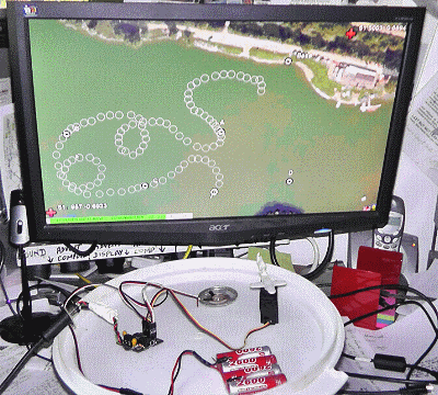
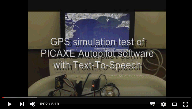
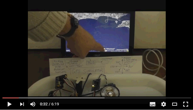
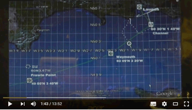
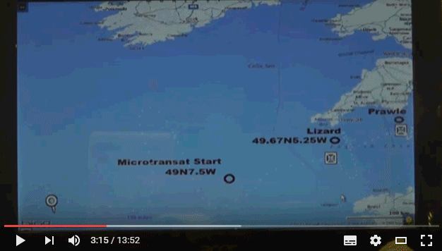
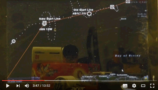
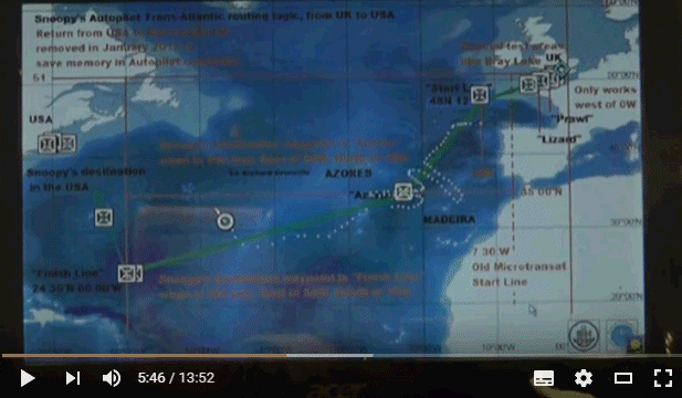
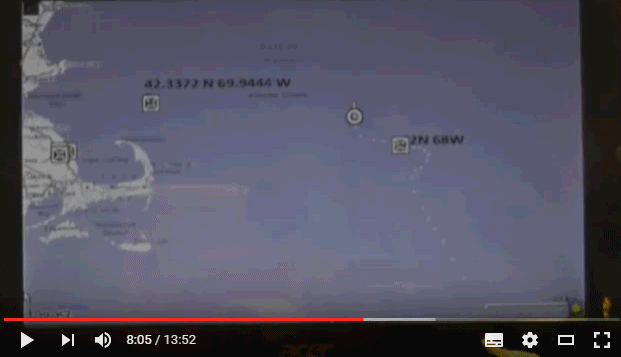
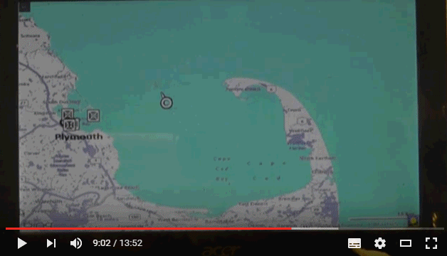
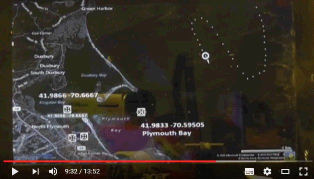
This picture shows use of Robin's "GPS Simulator" on his PC, to test the PICAXE autopilot software, particularly on it's planned route to the USA. The deliberately "wobbly" path, is created by clicking on maps with GPSS to make a file of NMEA GPS data. This data is played out of the PC COM1 RS232 port into the PICAXE, and also shown on the PC screen. The data is deliberately wobbly, to check that the Autopilot turns the rudder correctly, to reach the next waypoint. The PICAXE should beep out it's usual sounds, including range to waypoint and "Close Encounters" when in the waypoint "box".
Footnote in January 2013: Small changes have been made carefully to the PICAXE Autopilot software, and will get a lot of re-testing.
There is always the option of using exactly the same version (1) of the autopilot software launched in 2012 after months of testing.
However, it is hoped that this version (2) will be easier to test thoroughly, both on the water at Bray Lake, and sailing UK to USA
with the GPS simulator. This is because Text-To-Speech (TTS) is used to speak more detailed information such as: "270 degrees"
(waypoint is due west), "right 45" (turn right 45 degrees), "60 metres" (distance to waypoint) and "at waypoint". The other changes
relate to additional waypoints near the UK south coast, to avoid the busiest part of the shipping lane, and also reduce risk
of hitting the UK coast due to steering to a very distant waypoint.
There is now a 6 minute video of the software being tested with the GPS simulator
here.
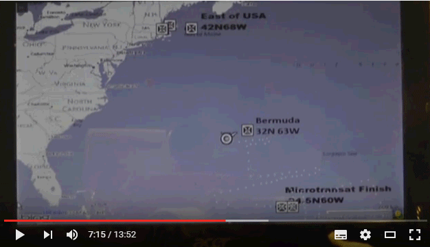
A more complete video of the end of Snoopy's planned journey is
here.
Footnote in July 2013: here are typical statements from the PICAXE AutoPilot program, showing signal/pin numbers used
for things like reading GPS data, rudder servo output, and text-to-speech (TTS) output. I've put them here
to aid discussion, on the PICAXE forum, of experiments with the HMC6352 compass module. We need to find one or two spare signal pins !
Footnote in July 2014: there is now more detail about "4. calculate the true heading from current GPS position to the destination position." on Snoopy's Software Page.
Added in May 2016 ...
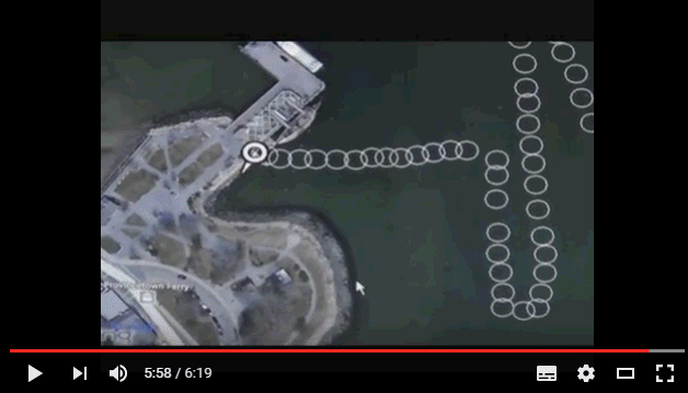
Here are four frames from the old 6 minute video explaining how the autopilot software is tested with the GPS simulator.
![]()
![]()
Here are some frames from more recent video of Snoopy's complete route simulation.
![]()
 This section provides more detail on the software action above, described as "8. move the rudder to turn the boat in required direction".
The autopilot steering logic has not been changed for years, including that used in boats 6,7,8, and 9. However, in September 2013, we've started to experiment with the "rudder trim logic", since this may result in improvements for future boats, for future years. See boat 6 on right.
The basic GPS-based steering involves the rudder normally being "straight ahead", but being moved to left or right, for a few seconds, every time around the cycle of typically 6 seconds. i.e. about 10 times per minute. The time it is held over depends on the boat's speed, so that it is not too sensitive at higher speed. Numbers used, for Speed in knots S, have been: 1.5 sec + 1 sec (if S < 1) + 1 sec (if S < 0.5). i.e. 1.5 secs if speed greater than 1 knot.
The ammount of movement is proportional to the error in direction, between the target heading, and the GPS heading. i.e. the rudder remains central if the boat is heading in the required direction.
The "gearing" between direction error (+180 to -180) and rudder movement, has used a software "MAXDERR" value of 120 for years, after first experiments with values such as 90. e.g. if the direction error is 120, full rudder will be applied: if 60, half rudder, etc. i.e. rudder = maxrudder * error / MAXDERR. If the direction error is greater than MAXDERR, it is limited to this value. i.e. full rudder. This MAXDERR value is being looked at again, for future boats. e.g. maybe smaller, to give "tighter" steering.
However, instead of the rudder being returned to an exact centre position, every cycle, it is given some trim, in the direction of the turn. This was introduced years ago, to aid "self-balancing" of the boat in a wide variety of relative wind directions and speeds. If the direction of the turn changes, then the rudder trim is reset to zero. So, if the boat is repeatedly trying to turn right, the autopilot will gradually apply right rudder trim, in addition to the regular "right rudder".
Parameters in the software have not been changed for years, and these are:
These parameters have worked well in a wide variety of boats, including boats 6 to 9, sailing sloops of 3 to 4 foot long, but also on the small, motorised "windmill boat" of only 1 foot long. This is because there is plenty of adjustment available between boats, such as the size of rudder, and where the servo linkage clips onto the rudder lever.
Experiments with the compass (see "Alternative Designs" below) have led us to experiment with this GPS-only steering logic. e.g. modification of those numbers above and/or adding logic such as a "turn through downwind" if maximum trim is reached. It is thought that this might improve the sailing ability of the boats, including turning between "tacking" directions, into wind.
We will add more detail here, if changes are found to be worthwhile.
This is only used for testing, at home and on Bray Lake, and will not go to sea.
 During testing on Bray Lake, sound has been transmitted to shore to help us monitor the autopilot, since we first started in 2008.
e.g. "60 metres from waypoint", "turn left", etc.
In the early years we used a Pocket PC, speaking with recorded voice. We transmitted over Personal Mobile Radio (PMR), which has
a range of a few kilometres. Later we switched to FM radio, which was simpler and had sufficient range of 100 to 200 metres.
After we switched from Pocket PC to PICAXE computer, we switched to "beeps" to give the information. e.g. "dah dah dit" = 50+50+10 = 110 metres.
For boat 9 we will use text-to-speech (TTS), which can give more detailed information. Here is a video which shows these three methods:
Robot Boat Sounds....
During testing on Bray Lake, sound has been transmitted to shore to help us monitor the autopilot, since we first started in 2008.
e.g. "60 metres from waypoint", "turn left", etc.
In the early years we used a Pocket PC, speaking with recorded voice. We transmitted over Personal Mobile Radio (PMR), which has
a range of a few kilometres. Later we switched to FM radio, which was simpler and had sufficient range of 100 to 200 metres.
After we switched from Pocket PC to PICAXE computer, we switched to "beeps" to give the information. e.g. "dah dah dit" = 50+50+10 = 110 metres.
For boat 9 we will use text-to-speech (TTS), which can give more detailed information. Here is a video which shows these three methods:
Robot Boat Sounds....
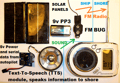
The picture on the left shows the completed transmitter box, and that on the right shows the bits used for it's construction. Only the Text-To-Speech module is new. The other parts were used in previous
years and seemed to work OK - either when relaying to shore the speech from a Pocket PC, or beeps from the PICAXE autopilot.
The two small 6v solar panels seemed to gather enough power to keep the PP3 9v battery charged, so the FM bug transmitter ran continuously
when we'd progressed to 24/7 testing. The FM bug draws about 10mA from the rechargable 200mA battery. i.e. about 10 hours without solar panels.
We experimented with several types of transistor radio over the years, and the best was also the cheapest: �2.50 from Tesco ! :-)
The TTS module was the "30016 Emic" from Parallax in USA. Sadly, the TTS module was expensive, including import duty, and that's the main reason it's not going with Snoopy across the Atlantic ! :-) However, this recent addition has already proven it's worth, when used to test the autopilot on the GPS simulator. See footnote in the software section above for a video of this.
 Here are some tips on where we got our products and materials:
Here are some ideas on how my design may eventually get modified or changed - including back
to some of my early ideas from my first thoughts in 2008, like the electronic compass.
Thanks to those whose emails have spurred these thoughts.
During August 2013, experimental work was started using an electronic compass. Details of this work are on the Compass page, which was expanded in July 2014, after starting work on a much better, tilt-compensated, compass. This work was closely coupled with use of a different, 28X2 Picaxe computer, with twice as much memory. Experiments were started on techniques such as "Power Switching" the sensors, such as compass and GPS, and even the servo, that moves the rudder. Another old page that may receive attention again soon, is the Wind Direction Sensor page. We got the solution to work, including "tacking logic" in the software, but after trials, the wind direction sensor was removed, because the power it consumed was not justified by significantly better upwind sailing performance.
 This experimental work is not relevant to the existing design, used in boats 8, 9 and 10, but it might be used in future boats.
If you go back to my earliest thoughts in 2008, you will see I was thinking of a flux gate compass, to sense where the boat
is pointing, for the autopilot steering. Our simple GPS solutions use, instead, the direction the boat is moving - which is not
the same thing. Things like the tide can "confuse" the autopilot. We can live with this design limitation, but, if we wanted to perform
a sailing mission such as "sail around the Isle of Wight" - we would need to have an autopilot that would handle the tide better.
However, the main benifit of the compass is probably to allow power switching of the GPS, with the consequent reduction
in power consumption, numbers of solar panels, weight and cost of the boat.
This experimental work is not relevant to the existing design, used in boats 8, 9 and 10, but it might be used in future boats.
If you go back to my earliest thoughts in 2008, you will see I was thinking of a flux gate compass, to sense where the boat
is pointing, for the autopilot steering. Our simple GPS solutions use, instead, the direction the boat is moving - which is not
the same thing. Things like the tide can "confuse" the autopilot. We can live with this design limitation, but, if we wanted to perform
a sailing mission such as "sail around the Isle of Wight" - we would need to have an autopilot that would handle the tide better.
However, the main benifit of the compass is probably to allow power switching of the GPS, with the consequent reduction
in power consumption, numbers of solar panels, weight and cost of the boat.
The rough notes on the right were put here, in case I lost the paper original. Click on it for the bigger version.
I would describe the current experimental work as "research" rather than "development" :-)
Footnote on Saturday 25th October 2014: I started some tests, picking up from work in August. Right now there are three 28X2-Compass autopilots: one in boat 6, one in boat 11, and one on the tea-tray. Only the tea tray autopilot has the GPS and servo power-switching changes. Tests with a milliamp meter confirm that the first two still consume current in the ballpark of 60mA. i.e. switching from a Picaxe 2M2 to the 28X2 does not make a significant increase in power consumption: the Picaxe draws less than 5mA.
After fixing a short between pins 27 and 28, initial tests indicate power consumption in the ballpark of about 20mA when the GPS is off, and the boat is using compass steering, and about 60mA when switching on the GPS for a "navigation check". The better BR355-2 GPS only seems to need a second or two of power, before it tracks, and is switched off. So, if off for even 30 seconds, the average current for the GPS will drop to less than 10% of it's normal ~40mA.
Most of the 20mA is for the servo, so further reductions might be made by power switching of this - already working back in August 2014. But for now, we will keep it simple, and stick with just compass and GPS power switching.
Looking at the last experimental software change (AUTOPX1.BAS dated 22 Aug 14), it seems, for our first experiments with GPS power switching, the following rules are used: GPS power kept on if within 30m of target; switched off for 10 secs if 30m to 50m; switched off for 30 secs if further than 50m from target. The compass is used for steering when the GPS is switched off. These rules can easily be modified, after we get the power-switched autopilot working as it should. i.e. still doing it's job, tested on Bray Lake, and with significantly less power consumption than the existing 8M2 based systems.
So, in conclusion, far more experimental work is needed, including tests on Bray Lake, but it does look as if power switching of the GPS can reduce the autopilot power consumption by 50% or more. The boat 6 autopilot has been modified to include GPS power switching and the latest Picaxe software. The old BR353 was replaced by the later BR355-2 and we saw an immediate improvement in the time needed to start tracking, after switch-on: from about 60 seconds (indoors) to nearer 2 seconds ! This will be needed if the GPS switching is to be exploited.
Remember that this is all "background experimental work", while we wait to launch Snoopy in boat10 !
Not needed if above switching of Compass and GPS used, but this is from an email discussion with Mike earlier in 2014 ...
The idea of not having a control loop of about 6 or 7 seconds has occured to me, and our earlier Pocket PC - Winvane autopilot had a 60 sec loop that could have been much longer (out at sea) This set the wind vane to steer the boat, after calculation the direction moved from change in GPS position over the 60 secs. It also had logic to calculate drift due to tide - all on my old page by following links at bottom of page.
I suspect that a solution that does anything similar, might end up being a bit too slow to implement and test here. I have thought of it before - that GPS could be switched off for the majority of the time (when out at sea, and not on Bray Lake where waypoints are maybe 100 yards apart) and save a LOT of power, since it draws such a lot (details on my design page)
But I know how much time this would cost, making and testing the changes. The Ametes wind direction sensor was not too difficult, and worth the effort - even if we eventually removed it.
A solution that might be worth me considering, that I've considered before, is to put this back in and switch off the GPS for long periods, do the steering relative to the wind. Even if no tacking logic put back in. This would be based on smoothing of the wind direction. Probably roughly equivalent to the wind-vane-rudder approach, but by software.
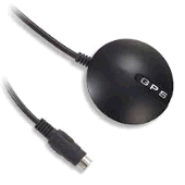 The Globalsat BU-355 GPS accounts for most of the autopilot power drain, that has to be
supplied by the eight solar panels. The GPS draws about 35mA, the picaxe computer just 1mA,
and the rudder servo about 7mA plus spikes when the rudder is moved: maybe 10mA average ?
This puts the total autopilot 5v power consumption in the ballpark of 50mA,
the majority of which is for the GPS.
So if we could find a lower power GPS, maybe we could reduce the power consumption,
needing less solar panels and allowing an even smaller minimum boat size.
The Globalsat BU-355 GPS accounts for most of the autopilot power drain, that has to be
supplied by the eight solar panels. The GPS draws about 35mA, the picaxe computer just 1mA,
and the rudder servo about 7mA plus spikes when the rudder is moved: maybe 10mA average ?
This puts the total autopilot 5v power consumption in the ballpark of 50mA,
the majority of which is for the GPS.
So if we could find a lower power GPS, maybe we could reduce the power consumption,
needing less solar panels and allowing an even smaller minimum boat size.
 On 5th April I made a breakthrough, with technical help from Globalsat in USA,
who told me how to use the SiRFDEMO software to put the BR-355 into power saving trickle mode,
and reduce the rate and type of NMEA data sent to the picaxe computer. I've already
proven that the method works, and have reduced the 35mA to less than 20mA.
The autopilot still works, without any change to my picaxe autopilot software.
On 5th April I made a breakthrough, with technical help from Globalsat in USA,
who told me how to use the SiRFDEMO software to put the BR-355 into power saving trickle mode,
and reduce the rate and type of NMEA data sent to the picaxe computer. I've already
proven that the method works, and have reduced the 35mA to less than 20mA.
The autopilot still works, without any change to my picaxe autopilot software.
More experimenting is needed, to find the optimum parameters input into SiRFDEMO, such as how many mSEC does the GPS switch off then switch on again, the NMEA message rate, etc. It seems as if we could reduce the 8 solar panels to only 4 in future boats. Also, our little yellow boat 6, used for first tests of the picaxe autopilot, with this minor change to the GPS, have sufficient solar panels added to make it "Atlantic Ready" :-)
My modification to the SPOT Messenger described above is very simple, and only allows the PICAXE based timer to initiate SPOT transmissions. However, thanks to Ian on the Microtransat List, we now know of far more sophisticated changes that can be made, permitting robot boats to send other data over SPOT communications.
I will not be using it, but others may find it valuable. See Hacking into SPOT and the SPOT Datasheet. Thanks Ian ! :-)
For years, and on all boats used in 2012, 2013, and 2014 Atlantic Attempts, we've used the same 130x130mm solar panels, purchased via FirstStopSolar in UK, at about �14. Each of the 8 panels, used for the 5v autopilot supply, measured 130x130mm and delivered a maximum of abot 250mA in direct, bright sunshine.
In 2014 I searched for alternatives, and soon found the bigger one, seen here next to Snoopy. It was purchased from Shanghai in China, so cost less, at below �7.40. But the important differences are in the increased power output (583mA), and reduced weight (75gm), without a great increase in size (165x135mm). I tested these when they arrived, and it looks as if the claimed power output is genuine. I suspect both types of panel originate from Shenzhen in China :-)
The practical result is that fewer panels are needed and the marblehead deck does not need to widened, to protect the panels. The result should be a lighter, and even less expensive boat. We expect to test these on Boat 11 in 2014 and 2015, to confirm the panels are reliable and do not deteriorate with time. The old 130x130mm panels have worked well, and I hope these new ones will be even better.
This section was moved from the front page in 2013. See the January 2014 footnote, and the low cost Mobius camera.
Several people have asked if we should put a camera on the boat, to send pictures or even video to the shore.
 It is tempting, and if you've watched the recent video, you will see reasonable quality video from this cheap key ring camcorder.
Our old videos showed video from cameras like this on Snoopy's boat. More expensive, professional products, like the GoPro Hero, are
often used on surf boards - but are approaching the cost of the rest of the boat, and would exceed Robin's "hobby budget".
Most important - a simple onboard camera is fine for Bray Lake, because we get the boat back afterwards. But, for Snoopy's Atlantic attempt,
we don't want anyone to touch his boat to retrieve a camera - or he might be disqualified.
It is tempting, and if you've watched the recent video, you will see reasonable quality video from this cheap key ring camcorder.
Our old videos showed video from cameras like this on Snoopy's boat. More expensive, professional products, like the GoPro Hero, are
often used on surf boards - but are approaching the cost of the rest of the boat, and would exceed Robin's "hobby budget".
Most important - a simple onboard camera is fine for Bray Lake, because we get the boat back afterwards. But, for Snoopy's Atlantic attempt,
we don't want anyone to touch his boat to retrieve a camera - or he might be disqualified.
![]() Some smartphones might have suitable "aps", and enable pictures or video to be sent back to shore, over the normal cellular GSM network.
Even our GPS bottles used GSM years ago, sometimes from several miles offshore - even though they were practically at water level
- Snoopy's deck is much higher, and we could use the mast, or a shorter pole at the back, where our removable FM transmitter was
(see design page). There may even be a smart satellite phone product, using Iridium, Thuraya, or Globalstar communications,
which could work far from land, in the middle of the Atlantic.
But then we are talking about "throwing away money" when Snoopy is lost at sea - which will always be
the probable outcome: the question is how far he gets.
Some smartphones might have suitable "aps", and enable pictures or video to be sent back to shore, over the normal cellular GSM network.
Even our GPS bottles used GSM years ago, sometimes from several miles offshore - even though they were practically at water level
- Snoopy's deck is much higher, and we could use the mast, or a shorter pole at the back, where our removable FM transmitter was
(see design page). There may even be a smart satellite phone product, using Iridium, Thuraya, or Globalstar communications,
which could work far from land, in the middle of the Atlantic.
But then we are talking about "throwing away money" when Snoopy is lost at sea - which will always be
the probable outcome: the question is how far he gets.
Some solutions are not difficult to design, using off the shelf products, such as an Iridium modem. However, Robin does not have the time to research, assemble, and demonstrate a complete solution, including it's power system. However, he is happy to tell someone sufficiently experienced what might be done (if he doesn't know already). That person would need to fund their own time, and obtain the required products to build the solution. Of course, some product manufacturers might choose to donate sample product. Someone (like a TV network or newspaper?) might decide to fund the few hundred pounds/dollars needed, to pay for the "materials costs" so the solution can be "lost at sea" - but after proving the effort was worthwhile ! Solutions that have already been discussed involve things like use of the Iridium Satellite comms system - which would enable pictures or videos to be sent back from anywhere, including the middle of the Atlantic, or when approaching Snoopy's secret destination in USA ! :-)
Anyone interested in funding or doing the technical work ?
January 2014 footnote: words and pictures based on a recent blog entry:
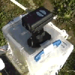 The big step forward was addition of a low cost Mobius video camera (on right), and we have a new video to prove it.
This "deck camera" provides excellent HD quality video,
with sound. You can just about hear the computer speaking above the splashing of waves and wind noise. You will even hear me shouting
from the bank. I'm looking forward to hearing what profanities the other sailors say, during close approaches :-)
The big step forward was addition of a low cost Mobius video camera (on right), and we have a new video to prove it.
This "deck camera" provides excellent HD quality video,
with sound. You can just about hear the computer speaking above the splashing of waves and wind noise. You will even hear me shouting
from the bank. I'm looking forward to hearing what profanities the other sailors say, during close approaches :-)
The new 14 minute video is
here and part of a frame from the Mobius camera is below. Clicking on it will also play the video.
Note that this box, under the Mobius camera, is only used for testing on Bray Lake, and is removed before the trip to the seaside, for an Atlantic Attempt. The box holds several items:
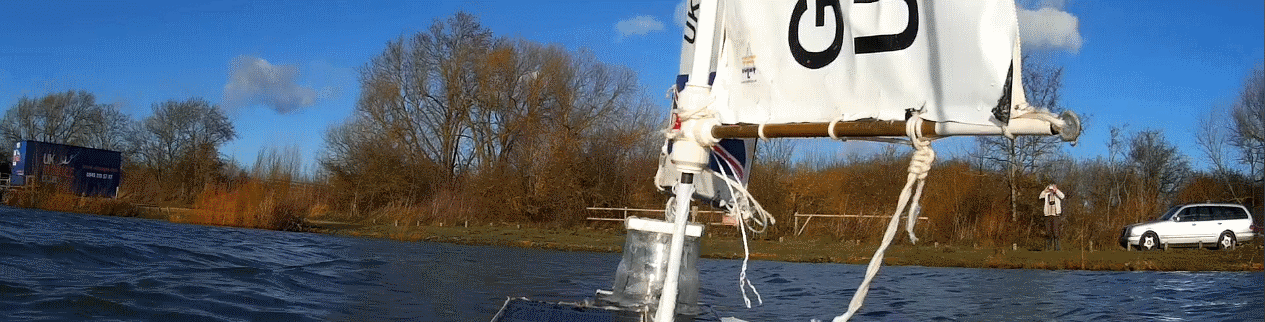
![]()
This is for those, such as on the Active Picaxe Forum , helping Robin build relacement Picaxe 28X2 autopilots, able to exploit the old, but thouroughly tested, autopilots used in Snoopy's Robot Boats for years.
Robin believes the latest version of the Picaxe 28X2 based autopilot software, used in Snoopy's Robot boats since December 2017, was version "Romeo", and the Picaxe 28X2 source code is here - in ap28x2r.bas is here .
When downloaded, and opened with a simple text editor, like Notepad, the first few lines should be those below ...
'AP28X2R.BAS 01Dec17 "Romeo" of Snoopy's Picaxe 28X2 Autopilot Software. (c) Robin Lovelock www.GPSS.co.uk
'AP28X2R.BAS 06Dec17 "Romeo" rudder gearing constant MAXDERR = 30 to 60 after today's test
'AP28X2R.BAS 01Dec17 "Romeo" Only change is rudder gearing constant MAXDERR = 120 to 30
'based on
'AP28X2Q.BAS 31Jul17 "Quebec" Correct cross trackj error by comparing W24 CBWP Course Between Way Points
'AP28X2P.BAS 16Jul17 "Papa" remove spoken range bug when ~ 100m E-W heard on 12th July 17.
etc, etc ...
![]() There have been
There have been
visitors to this page since 9th April 2016.

![]()
© 1991-2023 Robin Lovelock. Please credit www.gpss.co.uk if you use material from any of these pages. Thankyou.
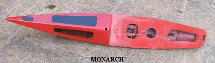